|
Return to Redbridge Wharf
Exhibition Train Control for Redbridge Wharf
The operation of the layout by DCC requires driver/operators
to know the DCC number for each locomotive they are driving. With over 30
different locomotives or trains on Redbridge, a method of advising the drivers
of their next duty was important.
It needed to be simple and achieved without voice, as exhibitions
can be noisy and mis-heard numbers would be embarrassing. We have a large track diagram with all track
shown that is used to set and cancel routes by means of push buttons. Routes
are displayed by a series of LEDs and repeater signals along the route chosen.
Most loops within the fiddle yard can hold two trains. The route setting is
controlled by the ‘signaller’.
 |
|
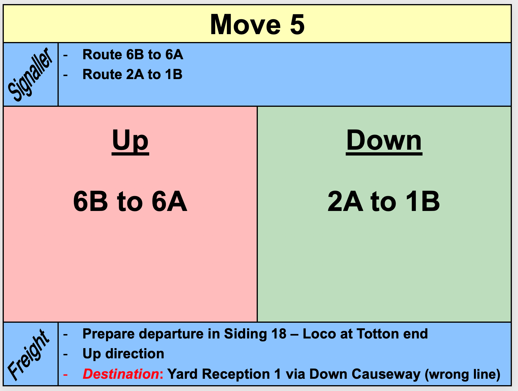
A sequence of 30 moves was developed, using power-point to
display the sequence on a screen so that the signaller and both the up and down
drivers could see what the next move would be, described as “start location/end
location”.
The 30 step sequence advances each train in the fiddle yard, and
there are 7 repeats of the sequence before the trains are back to their
starting positions. The powerpoint could not show the constantly changing DCC codes
required within a show. Operators similarly could not be expected to remember
every DCC code for every rostered loco. |
A prototype control used magnetic strips with DCC numbers hand
written using whiteboard markers. This suffered from difficulty in peeling off
the strip from the magnetic board to place the loco in service without erasing the all-important
number. This led to the current more sophisticated approach.
|
|
|
|
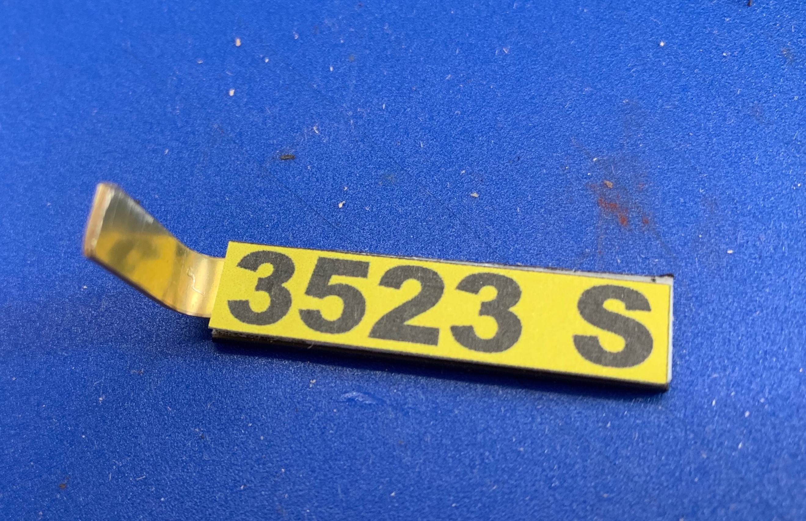
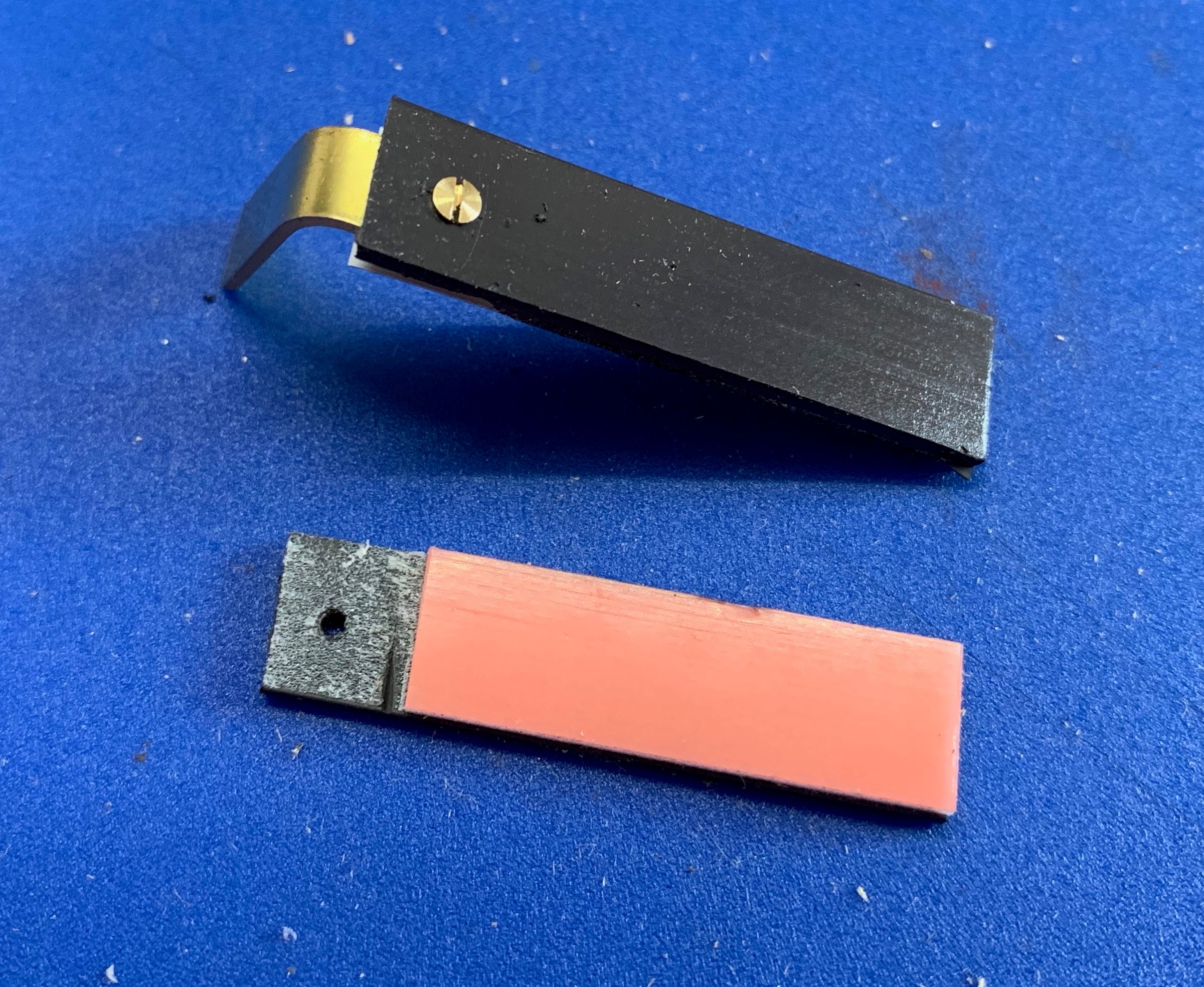
A magnetic strip which has a self-adhesive
pad attached, (available from Radio Spares part no. 846-339), is used. Each
loco rostered has its DCC address mounted on a 40mm x 9mm magnetic strip
attached at one end to a bent brass strip to act as a handle. It was important
to use a non-magnetic handle, so scraps of brass were used. The area where the
handle was to be fixed had the self-adhesive strip removed. The brass was
drilled and tapped for a countersunk 10BA bolt to pass through the magnetic
strip into the brass strip. The fixing needed to be robust so that failures
were avoided. |
|
|
|
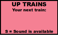
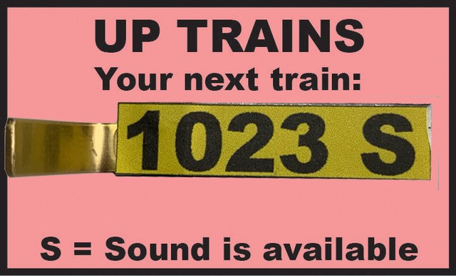
Each driver (up and down) has display board where his next
loco number will be shown. A small piece of steel sheet is attached to a post
angled towards the drivers' station, and has attached a colour coded notice. |
|
|
|
The numbers of locomotives were printed
in as large a font as possible (Arial Bold 29) and using Adobe Illustrator a
yellow background printed followed by the numbers. As space was available,
where a ‘sound’ chip was fitted an “S” was added to indicate the operator
should activate the sound before the train entered the scenic section, (and
hopefully would remember to switch it off on arriving back in the fiddle yard) |
The signallers process at a show is:
- Read the next move required.
- Set route
- Remove the loco numbered strip from the
departure road and place it on the display board for the appropriate driver.
- Once the train is on the move, remove the strip
from the drivers board and place in the arrival road.
|
|
|
The whole system may be digitalised in the future, but in
the meantime this system will provide error proof driving. |
Return to Redbridge Wharf
|